
I'm finally getting around to putting this CB450 engine back together. I've had a variety of obstacles this last year.
I'm going to try my hand at documenting the process - here goes:
One of the main things that draws me to the 450 is the torsion-bar valve spring mechanism. It speaks to me somehow.
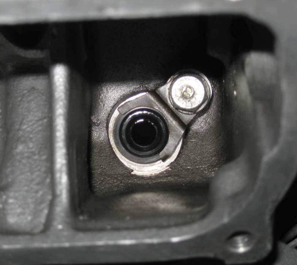
I've had the head spiffed up at my local machine shop. I've installed new valve guide seals, the original "cap" kind held down with the little fork-thing:
The torsion bar assembly goes in first. They come labeled "A" or "B". The A assemblies go on the right intake and the left exhaust. The Bs go on the left intake and right exhaust. These photos are of the right intake. Fish the splined tube in to the hole, and thread it through the valve closer fork.
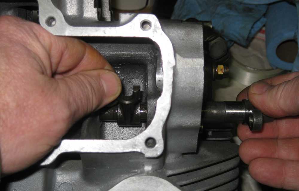
The fork will only engage the splines in the correct position. This shot shows the approximate relative position of the fork and the anchor arm where this happens.

It's a fine time now to stick the valve in, and see that the hook straddles it:
Let the anchor flop down

Drop the keeper ring over the valve stem, flat side down:

Put a speck of Vaseline (or other goo of your choice) on one of the keepers:

And place it on the valve stem, engaged in the grooves:

With both keepers in, you can rotate the torsion bar anchor up to see that the keepers are restrained in the ring:

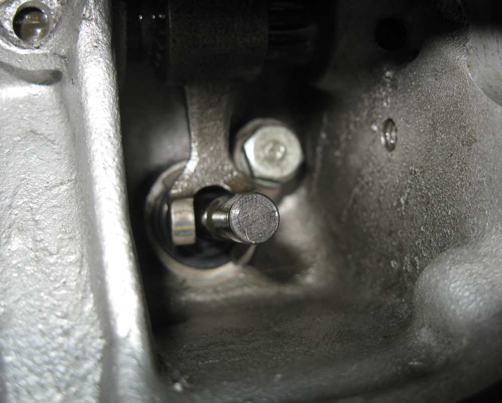
A 14mm open-end wrench works to load the spring by rotating the anchor until it lines up with the hollow pin. When it is, you can tap the works inwards:

And then put the bolt in

Now you can fish the eccentric follower shaft through its hole in the head and into a follower. Wish my fingers weren't so stubby...

The follower will lay right down on the valve stem:

Rotate the eccentric shaft until the mark on the end points to the camshaft axis. This makes the cam clearance as large as it can be:

Once the other side is done, the camshaft can go in. Orient the cam such that both lobes point outwards away from the followers. This way, you'll have clearance between the base circle of both lobes and the followers. Note the notch in the opening where my finger is on the right. The other end of the cam goes in first, and this notch is there to clear the cam for installation.
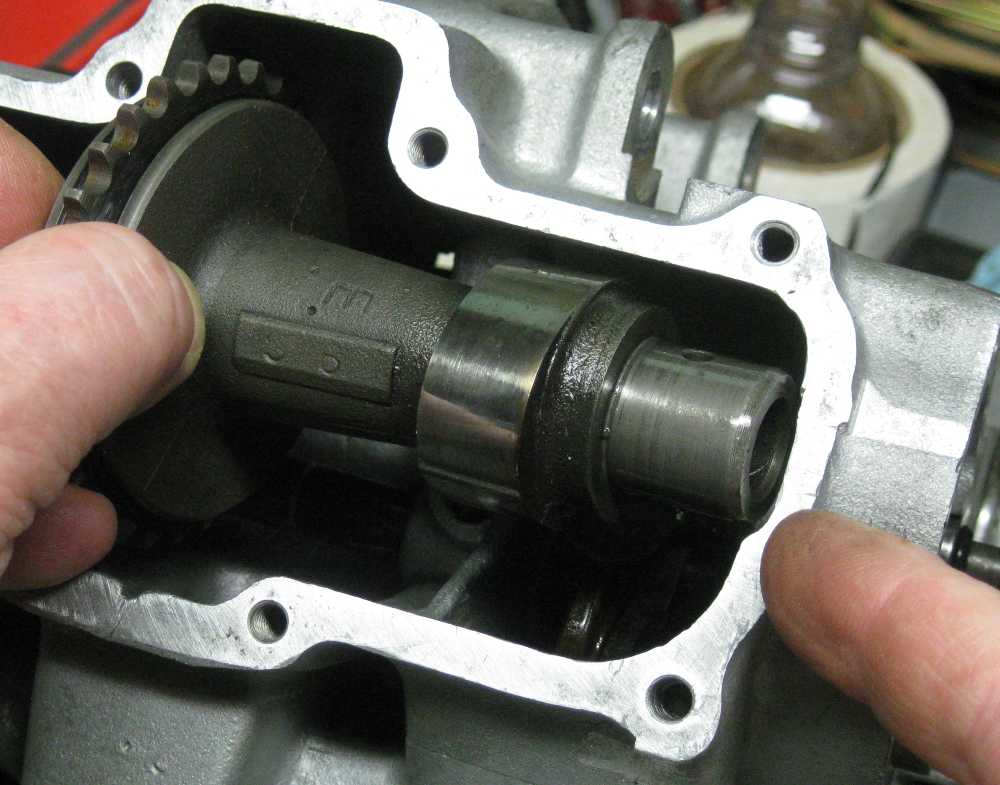
With the cam in, and the eccentrics away from it, the bearings can go on. Fidget with it until they slide in easily. If you have to force it, something is mucked up.

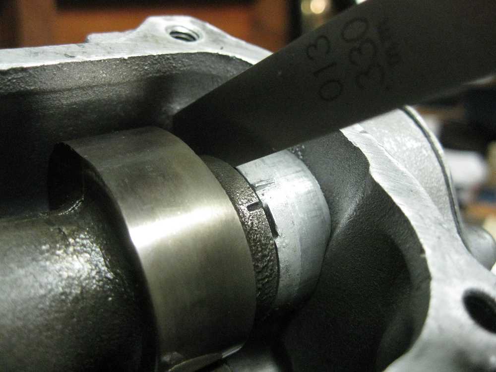
But wait! There's more! The axial play of the camshafts should be between 0.05 and 0.35mm (.002" and .014"). Once you tighten the cam bearing screws (with your new gaskets) you'll be able to measure the clearance with a feeler gage. Mine here is .013". I'll get a shim from my dealer, who has them in .1mm and .2mm thicknesses, and I'll have the option of moving my clearance closer to the middle of the specified range.
Also, the intake cam will be close to the alignment position needed to get the cam chain on. You can see the alignment marks in this photo too.
The exhaust cam is will need the same endplay adjustment routine. The alignment mark is a little harder to get to, as it is on the other side of the cam. Here's why: The index mark on the crank puts the Left piston at top dead center, but not between a compression stroke and a power stroke, as you'd think. Mr. Left is between an exhaust stroke and an intake stroke. That's why the timing mark won't quite line up on the intake cam - it should be already beginning to open at that point. Mr. Right trails Mr. Left by 180 (crank) degrees, or 90 cam degrees. When Mr. Left is at TDC, Mr. Right is at BDC, between a power stroke and an exhaust stroke. Since Left is just ending an exhaust stroke and Right is just beginning one, both exhaust valves are open a bit when the exhaust cam is at timing (chain install) position. So somehow you need to rotate the cam from the position where it was easy to install to where the index marks line up, with both exhaust valve open a bit. I horsed mine around with a screwdriver prying against the sprocket teeth. Crude, yes, but effective.

I didn't bother with new gaskets (bearing caps), seal (distributor drive), O-rings (on the outside of the eccentric shafts), or lube for these photos. I will do so when I put it together for real.
")