Honda Twins banner

1971 CB175 K5 Restoration

199K views 185 replies 44 participants last post by  CB2NR  
#1 ·
Got this bike about a year ago and finally got time to take her apart. The plan is to keep it stock with OEM parts. It won't be a short term project. Hope to have it done by spring 2013.

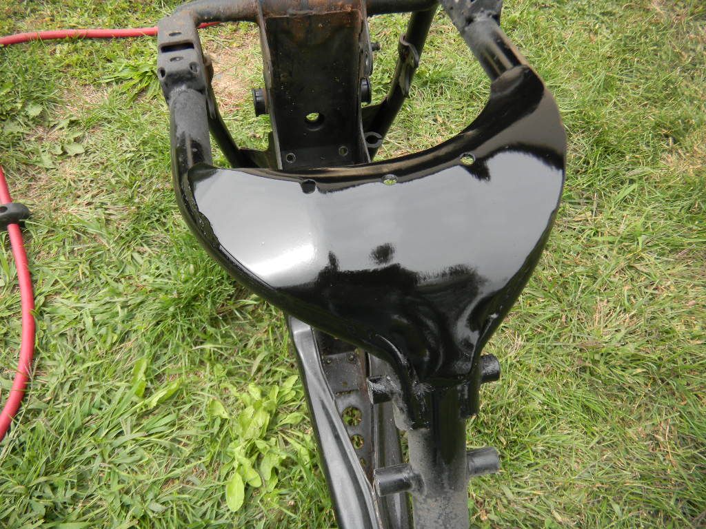
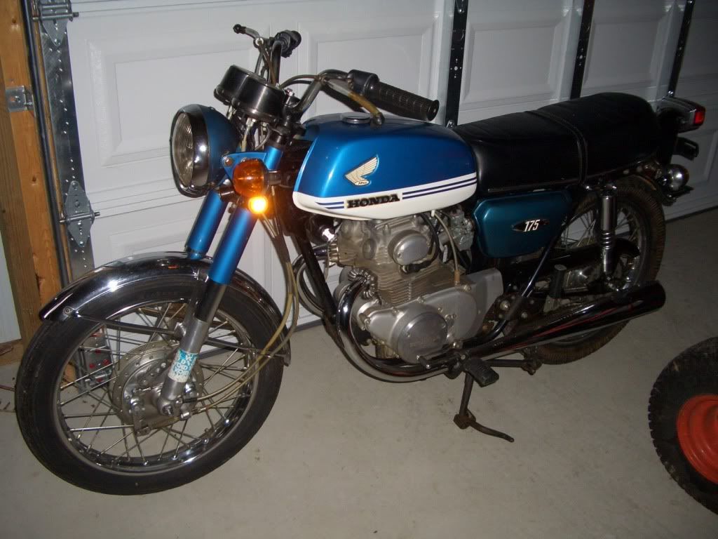
Here she is just after I got it. Looks good from 20ft. Attempted to start it and ran on only the left cylinder. Corrected the stuck float valve on the right and it ran. Not good, but it ran :D
Image


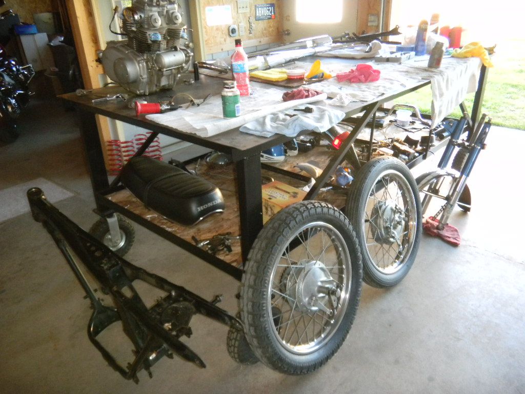
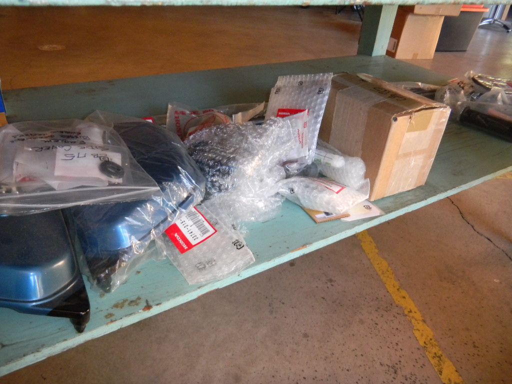
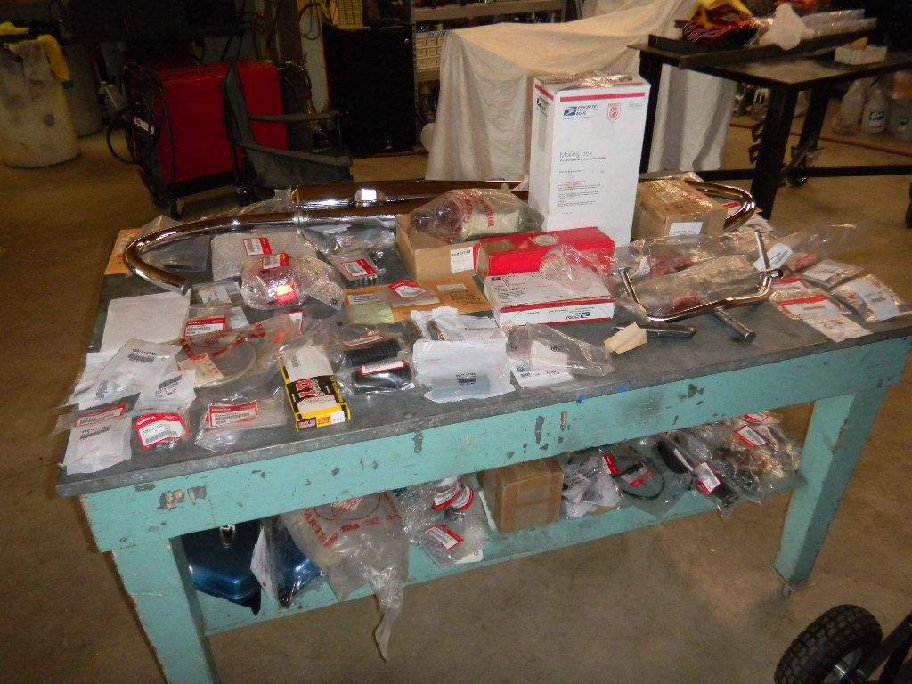
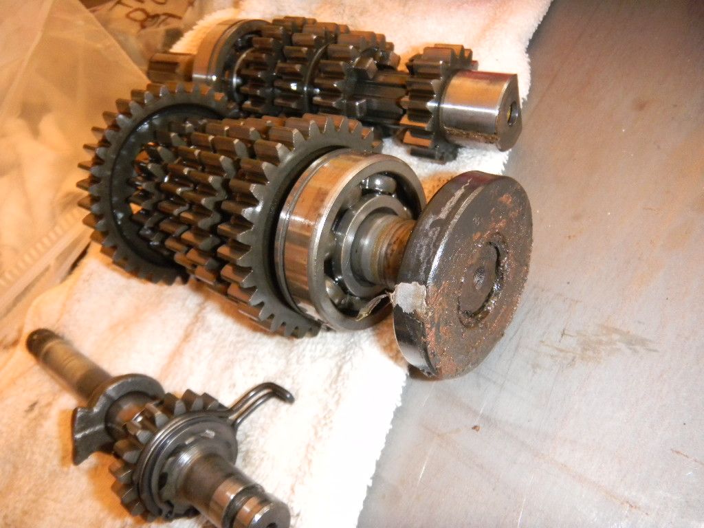
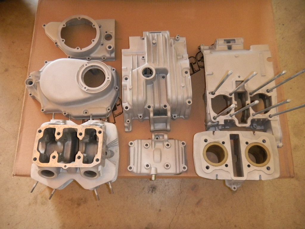
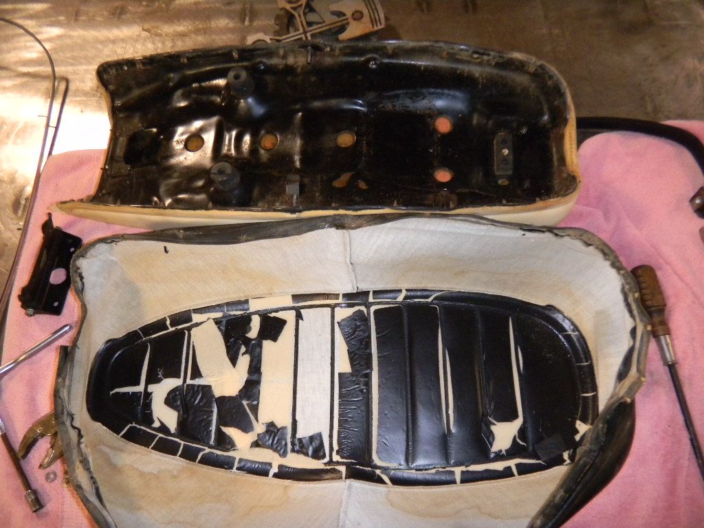
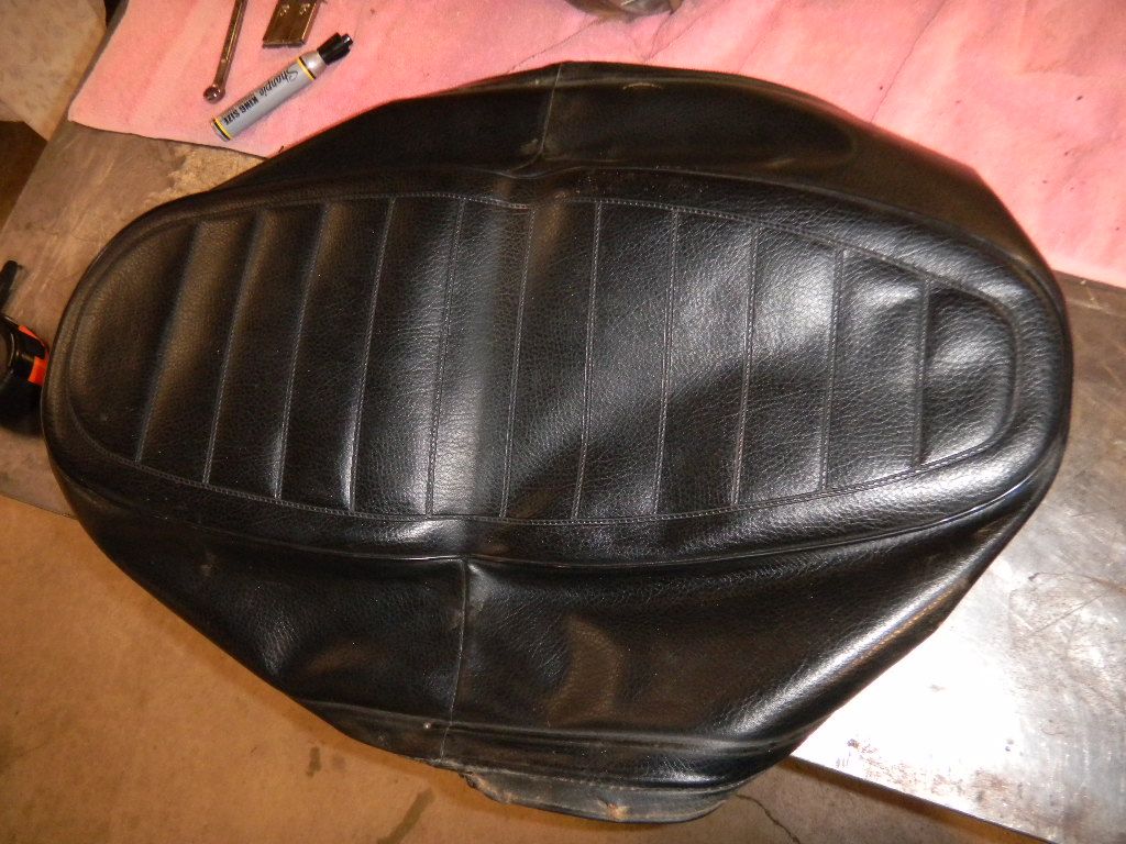
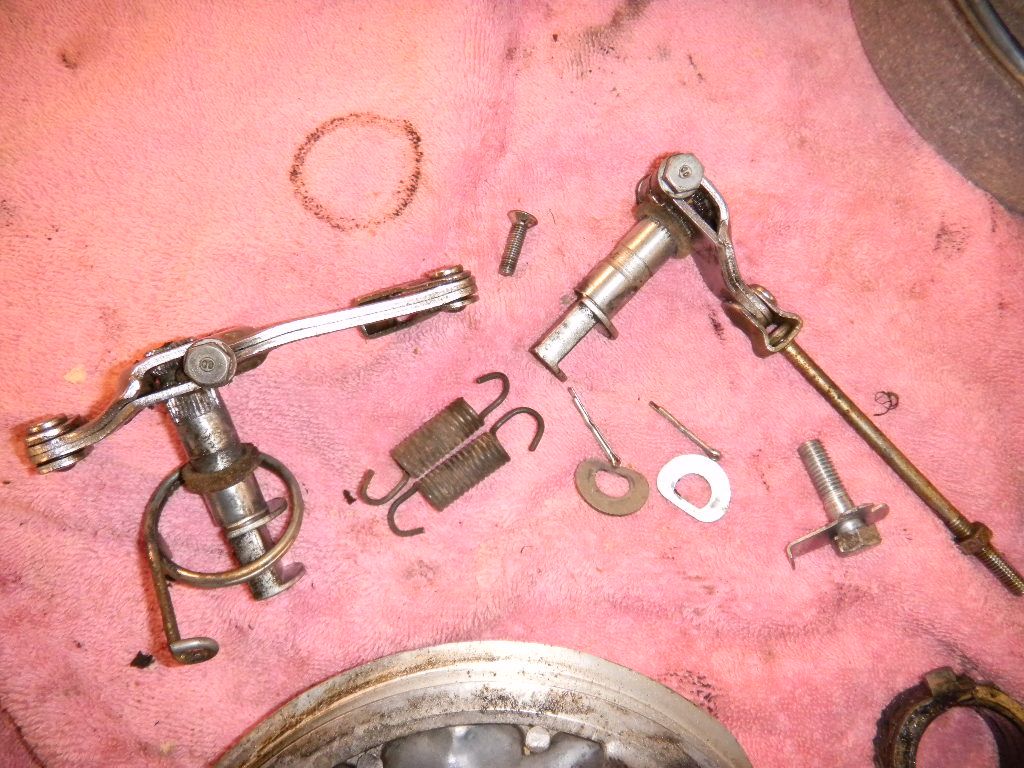
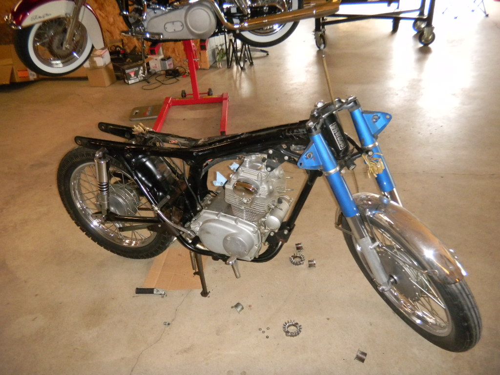
After about 2 hours of pulling & categorizing parts. Hope to have it down to the frame soon.
Image


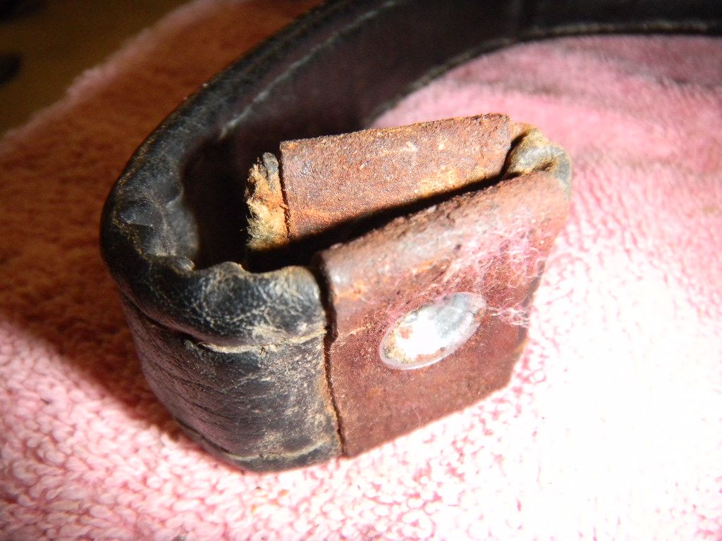
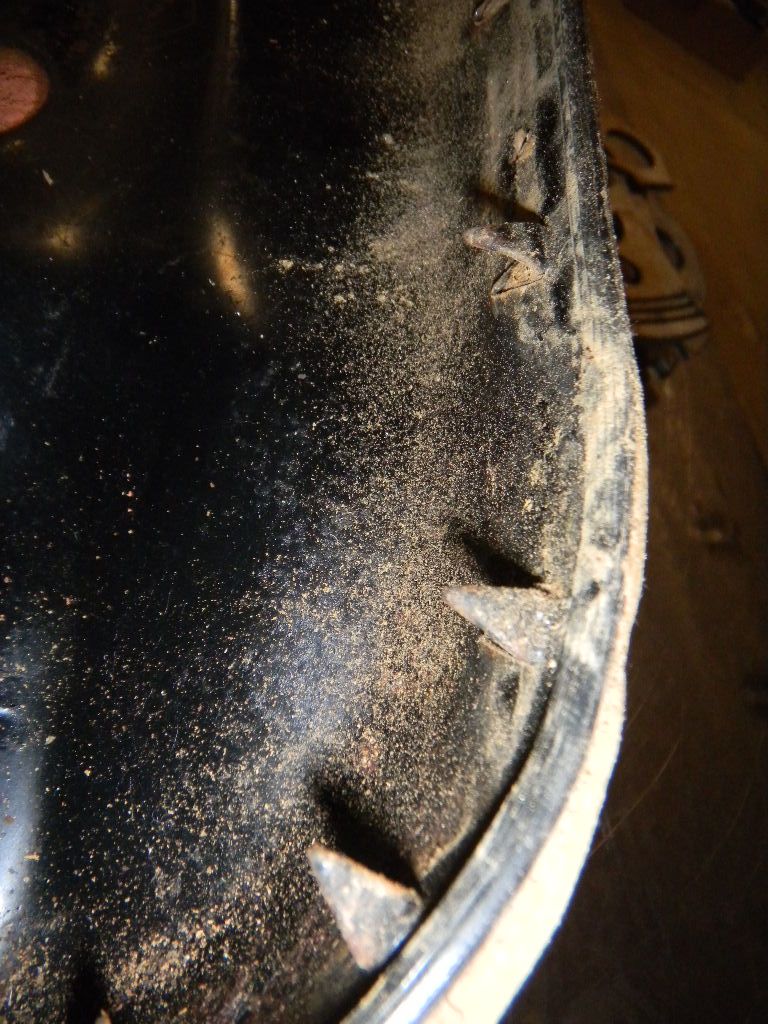
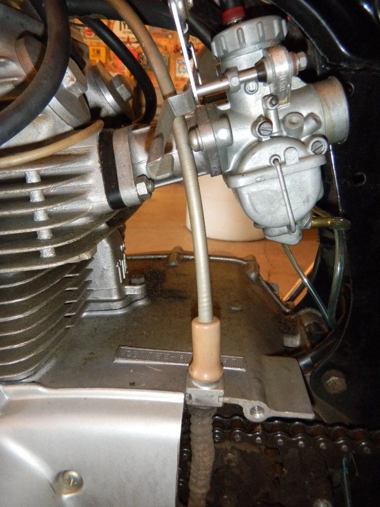
Carburetors were cleaned by the PO. The fuel tank is very corroded & rusted through in several places underneath, not sure I'll be able to save it.
Image


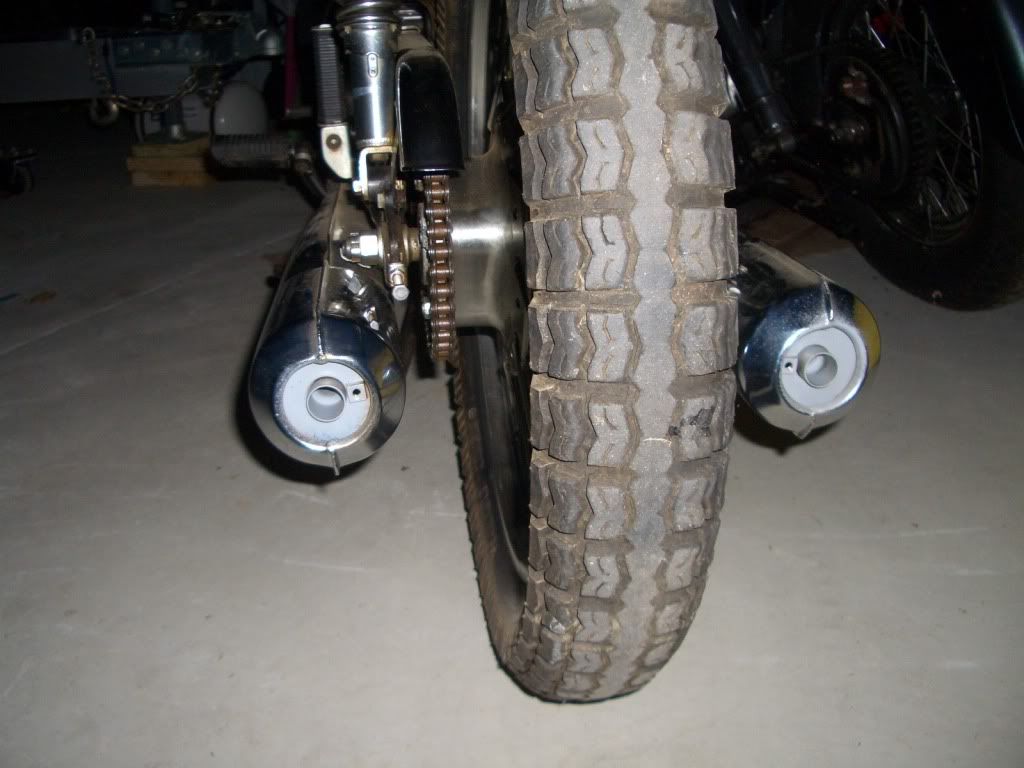
Exhaust are OEM NOS by the PO
Image


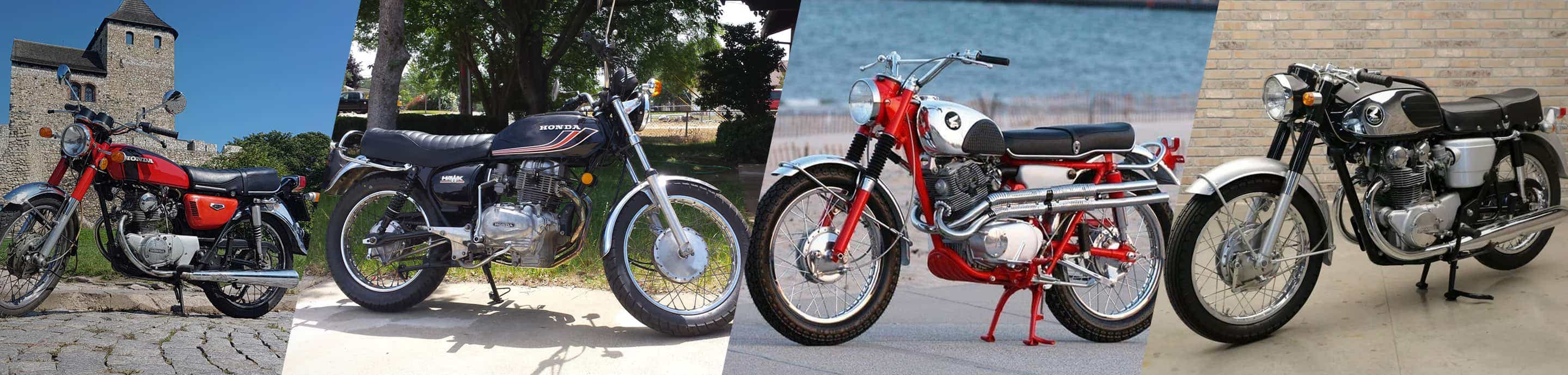
I like Candy Blue, but Candy Ruby Red is the color of the '71 CB175 I had. We'll see which color wins out.

Questions...
- what brand of engine gasket sets are recommended and which one(s) should I stay away from?
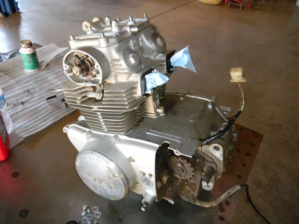
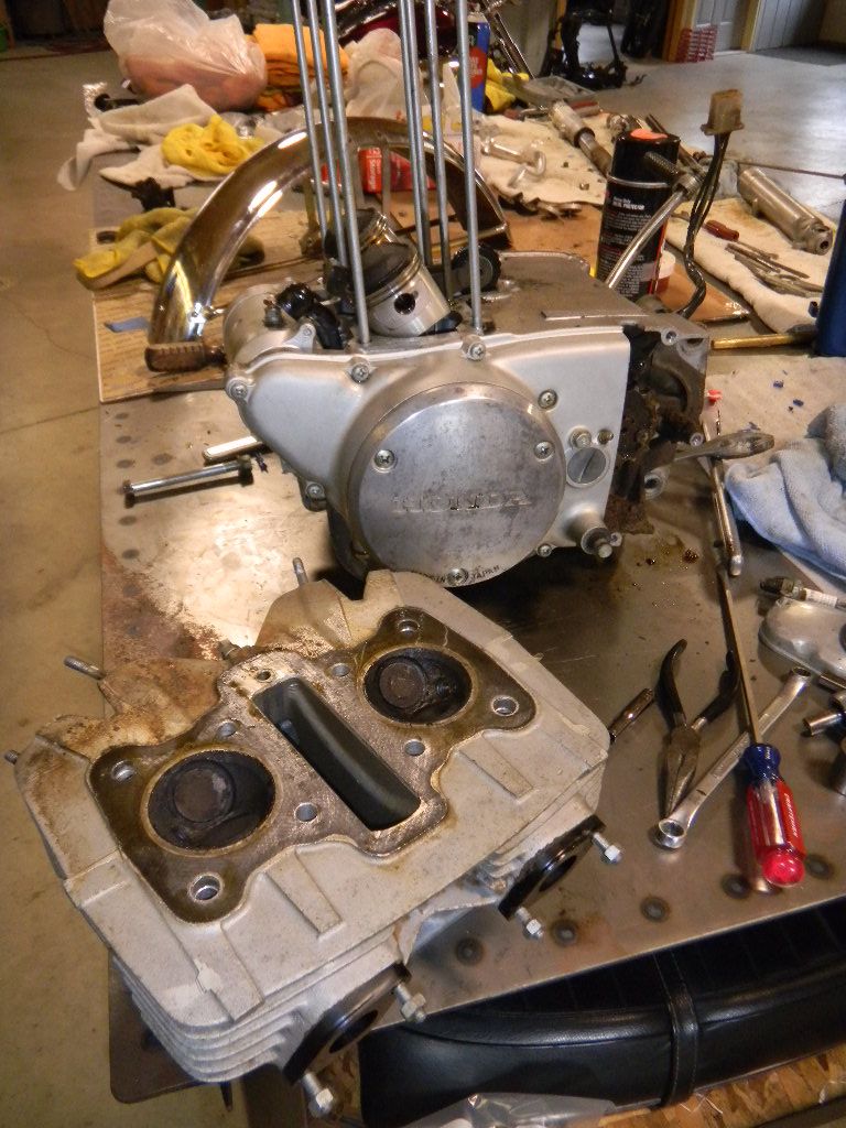
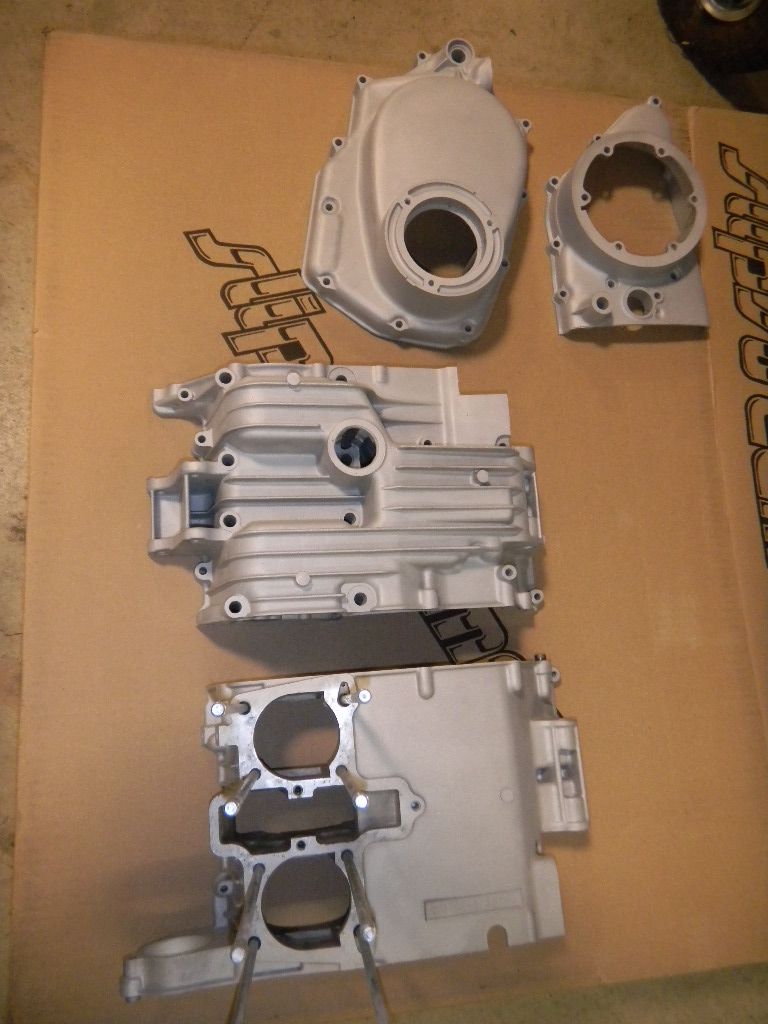
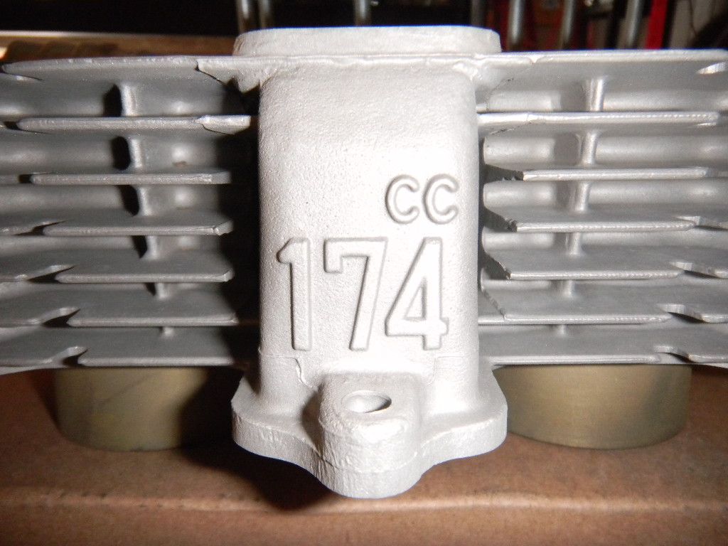
- I assume the engine was painted Honda Cloud Silver?
- where can I get a set of OEM tires (size and manufacturer)

Thanks!
 
#2 ·
Finally got it down to the basic pieces. Found it was used off road and several parts were bent (center stand, foot peg bracket, center stand pivot & rear brake pedal). I'll need to replace some of the parts, but can fix most of them.

The exhausts were probably damaged also, which might explain why new OEM mufflers were on it.
Image


Parts & pieces
Image


Image
 
#3 ·
Looks like a great 175 to restore, keep the pics coming.
 
#4 ·
Thought I'd take the bushings out of the swingarm before cleaning & powder coat. Ended up breaking off the first one I tried. They look to be made of carbon.
Image


Fork covers off revealed some seal leakage and plenty of dirt.
Image


Looks like they'll clean up good
Image


Been gathering parts
Image


Parts gathering is one of my favorite things. Must be the thrill of the hunt? The headlight case/bucket and seat are proving to be the biggest challenge.

The engine will get a good inspection with new seals & gaskets, along with any other part that needs to be replaced. The off road riding and spills ended up
 
#5 ·
Got most of the parts together for bead blasting & powder coat. Only piece missing is the seat pan.
Image


Started working on the forks. They were leaking pretty bad.
Image
 
#6 ·
Photo of an NOS kick stand and the one off the bike (was bent-straightened with press, cracked-ground spot will be welded, and someone welded an appendage-will be removed)
Image


I have a toaster oven to cure small painted parts. Put an ABP out on the VW forum and one of the members donated their oven (kitchen remodeling project). I'll use it for the engine cases and covers.

Oldie but Goodie :D
Image


Flapper wheels come in handy for cleaning up spots for scratches and gouges. 120 grit gets most of them out.
Image


The bottom leading edge of the frame after sanding and one coat of paint. The paint gives me an idea of what it will look like after powder coating. Still need to final sand with 320 grit.
Image


Exhaust are cleaned up. The left one has some scratches. Will need to do some research on how to clean them up (if possible).
Parts continue to come it.
Image
 
#7 ·
Took a break from the football games yesterday and got the top of the engine apart. Thought I could remove the head without taking the camshaft and rockers. Nope, rockers shafts hit the studs while pulling the head.
Image


The pistons look good, right one shows some signs of blow-by
Image


Oil, grease & some North Carolina dirt
Image


Memory isn't what it use to be and the detail shots help out latter
Image
 
#8 ·
If its not too late, make sure the swing arm bushings are out before powdercoat they're not carbon they melt (hindsight's a b!tch) I left them in because I couldn't find replacements and I was crossing my fingers that they would survive the heat (they don't) ended up with a block of teflon on the lathe.
 
#10 ·
Simo, thanks for the tip. Haven't taken the parts to be powder coated yet. I've tried to heat the swingarm and remove the bushings, but no luck. Need to try something else.

Thanks Nige, built the barn in 1992 and slowly started to finish it off inside. Its been a labor of love. My friends call it the "mancave".
 
#11 ·
More dis-assembly.

Took the clutch cover off. The three screws holding the oil filter cover on were difficult to get off (even with the impact driver)
Image


Image


Image


The centrifugal oil filter cover is really on there. I'll try heating the basket up with the heat gun and see what happens.
Image
 
#13 ·
Thanks, threading the 8mm bolt in worked great. Service manual had me pulling on the tabs with pliers. Good stuff, Thanks again!

Image
 
#14 ·
Pic showing the inside of the filter. There's some crud...

Image


Filter & one of the drive gears had to be removed to pull the pump and clutch basket
Image


Detail shot of gear, noting the raised edge
Image


Two bolts hold the oil pump in place
Image


Pump & basket being removed as a unit
Image


Image


Close up of pump intake screen and plunger
Image


Cases after splitting
Image


One windage tray removed, one still in place
Image
 
#15 ·
Took the transmission gear sets out, along with the kick starter shaft/gear.
Image


Neutral switch had to be removed before the shifter drum cold be taken out
Image


Screwed a bolt into the shift drum to help push it out
Image


Shifter mechanism had to be removed also
Image


Image


Used a bolt to keep all the parts in their respective order
Image


Shifter drum is held in with a metal keeper, held in with two screws
Image


Now it was time to pull the hairpins which kept the dowels in place for each fork.
Image


Notice that there's one pin missing...
Image


Couldn't get the last dowel out. Had to thread a tap in it, and it still didn't want to come. Ended up using a little valve grinding compound in the hole and slow turned it with a drill motor. About 5 rev's and started to work out.
Image


Now the drum was ready to come out.
Image


Here's a pic of the crankshaft assembly. Its a real piece of engineering. All roller bearings, even on the rods. No wonder its got a 10,500rpm red line :D
Image
 
#16 ·
Cleaned a bit today. First a bath in the solvent tank (mainly degreaser, water soluble). Idea was to get the big stuff off. The parts will get another cleaning later.
Image


Image


Image


After a few hours in the cabinet (glass beads). Not to worry, only the external parts were blasted. More cleaning & prep work for painting will follow
Image
 
#18 ·
Thanks John

Did some more cleaning

Before
Image


Image


Image


After
Image


Image


Image


Pic of valve layout (only parts missing are the washers or shims that go between the head and the springs)
Exhaust valves have two seals each - Intake none
Image


Image


Exhaust valve guide(s), checked out good :)
Image


Intakes were good too
Image


Misc
Image


Image
 
#19 ·
Not much progress, but thought the regulator needed some attention. Haven't tested it, hopefully it'll do its thing after I install it.

Here's a pic after a masked off the label
Image


Turned the air pressure down in the cabinet and took the rust & finish off. Painted with Stainless paint and used red touch-up for the screw and setting plug.
Image
 
#21 ·
Thanks Nige. Project will slow down a bit (family & house stuff)

Still looking for a headlight case/bucket. If anyone has or knows where to get one; please PM me - Thanks!
 
#22 ·
Getting ready to bead blast the frame & parts, but first had to remove the seat cover & foam so the seat pan can be cleaned up & powder coated

Had to remove the hinge. I think '71 was the last year for the rear hinge, later years went with a side hinge set up.
Image


Next came the seat strap. Chrome brackets are badly rusted.
Image


Image


Seat pan barbs had to be bent up, so the cover can be removed
There's quite a few, and luckily none broke off :)
Image


Seat cover
Image


Image


Now it was time to remove the foam. I thought this would be the easiest part. Nope... foam was glued/stuck in place.
It is cool seeing the different types of foam and how it was put together.
Image


Image


Image


Image
 
#23 ·
More seat stuff

Image


Image


Pried the brackets off... pretty rusty
Image


Bead blasting cleaned them up, but they were still bent
Image


Had a chuck of aluminum, happened to be the right size, just needed a hole
Image


Ready to clamp it in the vise
Image


Image
 
#24 ·
I am the proud owner of a 71 CL175. As a new owner, and a new rider, I am really impressed with your project. I can't wait for the next set of pics. I am not mechanically inclined, but feel as if I am in class, watching an instructor. Thanks for your great project report. I look forward to seeing more pics and progress.
 
#25 ·
CB2NR said:
Thought I'd take the bushings out of the swingarm before cleaning & powder coat. Ended up breaking off the first one I tried. They look to be made of carbon.
Image

You can put a hacksaw blade through the hole and reattach it to the saw handle once its inside. It may take a little elbow grease, but if you can make a cut on each side of the bushing down to the frame you'll be able to bust the rest of it out fairly easily. Once you have cuts made, a couple shots of penetrating lube will help free them up as well. I had to do the same thing with my honda civic control arm bushing a couple weeks ago.


,Tracy
 
#26 ·
papabear, Thanks, thought I'd give a bit more detail than most of the projects I've done. Glad to hear it might entice you to do your own. There aren't that many special tools and its great driving something you put together. Good luck & keep us posted.

Midwest, great idea - Thanks.
--------------------------------------------------------
Decided to work on the front wheel. Spokes looked good, but will need to clean them up and see. New ones aren't cheap.
Image


Took the spokes out.
Image


Rim looks really good with just a couple of small rust spots on the inside.
Image


Pic of the front brake hub
Image


Front axle
Image


Front brake assembly
Image


Image


Brakes are actuated through (2) mechanisms that work in unison.
Image


They have dimples that you line up for correct fitment - pretty cool!
Image

Image


Front brakes shoes are in good shape with plenty of material left - cleaned and ready for bagging.
Image


Speedometer drive gear is removed by turning counter-clockwise
Image


Exposing the driven gear which engages with the speedo cable
Not sure how to remove this assembly - looks like I might need to pull the pin to the right?
Image


Misc parts needing to cleaned
Image