Honda Twins banner

CD175 upgrade to 200cc, 12V, electric start, 5 speed gearbox

17K views 82 replies 8 participants last post by  goodoltup  
#1 ·
Hi all,
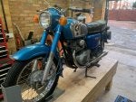
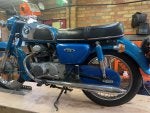
I'll use this as a project log for something I've had planned for a while. I have a 1976 CD175 here in the UK, for about 6 years now. It has a pretty nice patina, and has been mechanically rebuilt with new all new cables, tyres, brakes, bushings, etc. I just put new rear shocks on as well. (I should have documented that, but I bought some new shocks on Ebay from Thailand and swapped the blue covers to maintain said patina). The bike is a UK model with no electric start, and the kick shaft is worn out and it is very difficult to find a good replacement. The lights are WEAK and I would like a 12V upgrade with LEDs. It would also benefit from more power. And another gear. I would just drop in a CB200 engine, but I want to keep the single carb head. SO, let's just put a CD175 head on a CB200 engine.
Below is the bike.
 

Attachments

#37 ·
All tig welded up. It is now a little bent after welding, but can fix that with a brass hammer. All in all, very good.
Many thanks to my patient neighbour who donates his time and lathe for my motorbike projects!
 

Attachments

#40 ·
And by the way, anyone interested in this thread may also be interested in another forum blog I have going where I put a KTM 690 engine in a CB550 frame, see link below

 
#41 ·
The cylinders have been bored over 1mm and honed, and are on their way back to me. The nice man doing the boring sent some pictures, however, the cylinders fell off the jig and the corner fin was damaged. Not ideal, as these were a perfect set of fins. But, the chip is not that big, and in context I think it will be fine. I'm not doing a restoration. He has discounted the work (not enough to repair the fin) but I accept it and will just let it add a tiny bit of history to the machine.
When the cylinders are received I can do a parts fit-up and then start assembling the bottom end.
 

Attachments

#42 ·
All covers primed and painted. I did not paint or prime the alternator cover, but instead filled the Honda background with black enamel paint. When this has dried I will sand down the cover and clear coat it. Enamel paint may not have been the best choice, as it may remain sticky for some time.
Parts left to cool on the spare bathroom floor after being baked.
 

Attachments

#46 · (Edited)
The kickstart shaft pulled a little when welded, it was over 1mm out of round. I made up some quick aluminium blocks and straightened it in the bench vice. It was pretty effective, I got it to less than 0.15mm out of round but after that I was just chasing it so I stopped. The entire bottom end has been assembled now and I can confirm that it works smoothly with no binding.
The bearings that the kick start shaft run in have been a little mangled, and the retaining pin has somehow been sheared off. I was considering drilling a new hole for another pin on the other side of the bearing, because I didn't want to try and drill out the broken pin. Instead, I used the tig torch to make a small puddle on the exposed part of the pin, then just sunk the electrode into it and cut the current. The pin came out with the tungsten, it worked really well. The heat expanded the aluminium case enough to release it. Then I put a new pin in the existing hole.
 

Attachments

#49 ·
In the clutch cover, there is that oil system part that is retained by a clip, it was incredibly difficult to install. But then I had an idea. I smooshed an aluminium pipe to the right opening size to start the clip, and as I pounded the 'tool' down onto the cover it opened up and slid the clip on. Only took two minutes.
 

Attachments

#51 ·
A little work needed to be done on the stator wires. The plastic cover sheath was very hard and brittle, and there was some insulation damage on the wires. I removed the sheath and braided insulation and used heat shrink to support the wires, and replaced the sheath with some high temp cladding. I replaced the connector with a spare. Also replaced the neutral switch wire completely.
The CD175 wiring harness has no regulator, so relies on the electrical load of the system to keep the voltage in range. To do this it takes the central tap of the stator and runs it through the lighting switch, so it only contributes when the lights are on. I will be running a regulator/rectifier, so will need full voltage at all times. To bypass the CD175 lighting circuit I just combined the two stator taps together, which is how they would appear when the lighting circuit connects them anyway. That way I don't have to run new wires or disturb the harness.
 

Attachments

#56 ·
Extended the battery strap to accommodate the somewhat larger battery. Also mounted the new reg/rec under the battery box. Because the original rectifier was tucked up in the frame, the connector was in the wrong place for the new reg/rec position. Also, not sure what wiring harness this has in it. It does not seem to have been modified, but it also doesn't match with any diagrams or manuals I've seen. For instance, even though it is a UK bike, it has a yellow/red wire that goes from the headlight shell to under the seat. This is normally for the electric start button. (And I will use it for such). Also, the hot wire that goes into the coil, it would normally go into the same hot wire that feeds the horn. But on this bike, it is fed by a blue/white wire that comes from the headlight shell, which connects to a black wire anyway. So, I removed some redundant wires and cleaned things up. Also, the green ground wires need to be tied to the frame, because this normally happened on the old rectifier, whereas the new one is ground isolated. I had to stop because I ran out of spade connectors, but when they come I should be able to finish wrapping the harness in Teva tape and start testing. I really like chassis wiring.
 

Attachments

#57 ·
I'd like to thank you for providing top notch content to this forum. We've lost a few members in the past few months but gained 100 times more. Those that left have found their way back a few at a time. More will follow.

THIS is the HondaTwins forum!
 
#58 ·
^ Thank you Keith!
Quick one, completed the harness for the blinker indicator. Without the diodes the indicator won't flash because the circuit cannot ground itself as it does with incandescent bulbs. In this case, both halves of the blinker circuit (blue and orange) feed into the positive side of the new LED blinker indicator, and find ground through the green wire that is plugged into the harness. In the stock system, the blue side finds ground on the orange side and vice versa.
 

Attachments

#59 ·
Harness is complete and tested. I made a quick bracket to hold the LED winker relay. The engine had to go into the frame without the starter, which meant the cover had to come off. That's all back together now. The wiring harness has not been wrapped, that will happen after a test ride and verification that all electrical systems including charging are working.
 

Attachments